Here are some interesting points to note about Nipkow discs used to display
images.
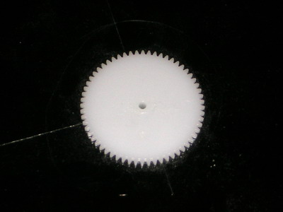
1. The picture is small compared to the size of the disc. Making the disc
larger will address this problem but rotating it at a speed of 750rpm becomes
more difficult requiring a more powerful motor and a greater possibility of
instability if unbalanced. Large spinning discs can be very dangerous if they
come off their mounting, Baird discovered this while experimenting! Smaller
discs are possible but require very tiny scanning holes which need a very
bright light source and the picture is really too small for normal viewing.
A magnifying lens is often used to make the picture appear larger.
2. The material the disc is made of is important. It must not deform significantly
while spinning and not be so flexible that it wobbles around excessively as
it gains speed. To some extent spinning the disc makes it more rigid. The
material must be easy to cut and drill with precision and be thin, ideally
thinner than the diameter of the scanning holes - really a rather demanding
set of requirements! 12" records were a firm favourite at one time. The
NBTV club have supplied discs made from sheets of 2mm thick Darvic (a type
of plastic in sheet form which has many of the desirable properties) and these
are the ones I've used for my experiments (see above). Unfortunately they
may not be currently available. The best discs I have seen operating are made
from stainless steel but this is an expensive option. Some people have experimented
using photographic film, basically photographing a picture of the required
scanning holes. This approach appears to have a number of advantages but there
are a number of technical problems which make it difficult to obtain good
results in practice.
 3.
When mounting the disc on a motor or bearing it is important that the centre
of the disc (relative to the spiral) is aligned with the central axis of rotation,
otherwise the picture displayed will be distorted. This is difficult to achieve
unless some careful planning goes into the way the disc will be mounted on
the spindle and the positioning of the scanning holes relative to this. The
Darvic discs from the NBTV club came with a nylon gear wheel attached to the
centre which is a friction fit on the 2mm spindle of a cassette recorder motor.
I assume the gear wheel was attached first and then the disc rotated on a
2mm spindle while the scanning holes were drilled, ensuring their correct
positioning. Place the mouse cursor on the picture to see the other side of
the gearwheel which is threaded and secured by a nut.
3.
When mounting the disc on a motor or bearing it is important that the centre
of the disc (relative to the spiral) is aligned with the central axis of rotation,
otherwise the picture displayed will be distorted. This is difficult to achieve
unless some careful planning goes into the way the disc will be mounted on
the spindle and the positioning of the scanning holes relative to this. The
Darvic discs from the NBTV club came with a nylon gear wheel attached to the
centre which is a friction fit on the 2mm spindle of a cassette recorder motor.
I assume the gear wheel was attached first and then the disc rotated on a
2mm spindle while the scanning holes were drilled, ensuring their correct
positioning. Place the mouse cursor on the picture to see the other side of
the gearwheel which is threaded and secured by a nut.
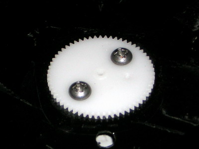
4. If the nut cannot be tightened sufficiently to stop the disc moving around
the gear wheel drilling two holes and adding two small nuts and bolts can
provide a solution.
5. Nipkow discs often have additional holes in them not related to disecting
or reconstructing the image. These are included so that optical switches consisting
of an LED and phototransistor can be used to detect when these holes pass
by. This allows the speed and rotational position of the disc to be determined
by electronic circuitry providing a means of automatic synchronisation. These
holes are often relatively large compared to the scanning holes, typically
3mm diameter, so the casual observer looking at a disc will often notice these
first (and may not even notice the scanning holes!)
6. In the first picture above you can see one of the synchronisation holes
is covered with tape. This may help lock the picture in the correct position
since it corresponds to the missing sync pulse in the NBTV club synchronisation
standard.
7. The Nipkow disc produces an image which is not quite rectangular because
each scanning hole is following a circular path. The picture reproduced is
not distorted if a similar scanning disc is used in the camera.
8. If the disc is not truly circular relative to the axis of rotation or
significant material has been removed it may not be balanced and vibrate when
rotating at speed. This could be dangerous and will degrade the picture so
it may be appropriate to balance the disc. This can be done with the disc
vertical without running the motor by slowly rotating the disc by hand and
determining which side seems heavy, preferring to be at the bottom. Then by
removing disc material (perhaps with a drill) or adding weights (which must
be attached so they will not fly off) at suitable positions this can be counteracted
and the disc balanced. This is not a trivial task and fortunately I have not
needed to do this with my discs.
9. After the holes are drilled being so small they may be difficult to clear
of all debris. A fine wire poked through them is probably the best bet. Great
care should be taken not to do anything to the holes to change their size
since this will almost certainly make them random sizes allowing different
amounts of light through them which exaggerates the line structure on the
final image.
10. The scanning holes are usually made circular because these can be made
fairly accurately using a small drill bit. There is a strong argument for
making the holes square since this allows extra light through and more uniformity
across the line profile. However these are more difficult to make accurately
and usually requires a metal disk and a square punch (perhaps one with the
sides filed flat). Not recommended for a beginner.
11. A 12" disc has a lot of mass associated with it and air resistance
when turning. Some regions of the disc can be cut away to help minimise these
effects essentially producing a disc with wide spokes. Depending on the material
used it is important to avoid cutting so much away that it loses its mechanical
rigidity.
12. Making your own disc is not a trivial task and takes a lot of time and
care. If you are good at making models you probably have the right skills
and equipment for making a Nipkow disc. The rest of us just have to struggle
or buy a ready made one.
13. Although it is common to attach a Nipkow disc directly to a dc motor
better performance may be obtained by mounting the disc on a separate bearing
and using a rubber drive belt between pulley wheels attached to the motor
and disc. By having a smaller pulley on the motor it can run closer to its
optimum speed (typically around 3000 rpm) which will increase the power available
to turn the disc. A popular (and low cost) precision bearing used in this
arrangement is the drum head out of a discarded video recorder.
14. Many constructors attach a stroboscopic disc with a total of eight black
and eight white segments since this appears to stand still when the rotational
speed is correct viewed under mains lighting (with 50Hz mains and 750 rpm).
It doesn't have to be particularly large but it needs to be centred on the
axis of rotation.